

Extended Reality can make industrial training more visual, contextual and interactive. Instead of reading a manual or watching a generic animation, a trainee can see digital instructions directly inside the real workspace. But for this guidance to be truly useful, the XR system needs to understand more than where the user is looking. It needs to understand where the real object is.
This is the challenge addressed by the D-Cube’s Vision Module: enabling an XR application to recognise, track and align digital guidance with real industrial components.
The current Vision Module prototype focuses on synchronised RGB-D perception for XR assembly tracking. In simple terms, the XR device captures the live camera image, depth information and headset pose; the server reconstructs the correct RGB-D observation; AI services identify and track the selected object; and the result is sent back to the headset as spatial feedback.
This makes it possible to move from generic XR overlays to object-aware XR guidance.
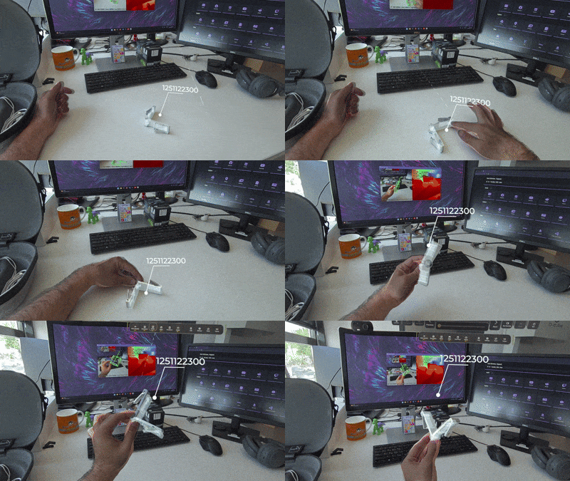
Vision Module Overview
Why Object-Aware XR Matters
In industrial training and maintenance, alignment is not just a visual detail. If a virtual arrow, 3D model or instruction is slightly misplaced, the trainee may hesitate or lose confidence in the guidance. This becomes especially important when the task involves precise assembly steps, small parts or components with specific orientations.
The Vision Module helps address this by estimating the 6D pose of a real object. This means the system does not only detect that an object is present; it also estimates where it is, how it is rotated, and how digital content should be placed relative to it.
A practical example is aluminium profile assembly. If the Vision Module knows the pose of a real aluminium profile, the XR application can animate a mechanical corner entering the profile with the correct position and orientation, without the trainer or developer manually aligning that animation in the scene.
The same capability can support many other scenarios: assembly error detection, step-by-step validation, maintenance guidance, and remote expert annotations that remain anchored to the real component.
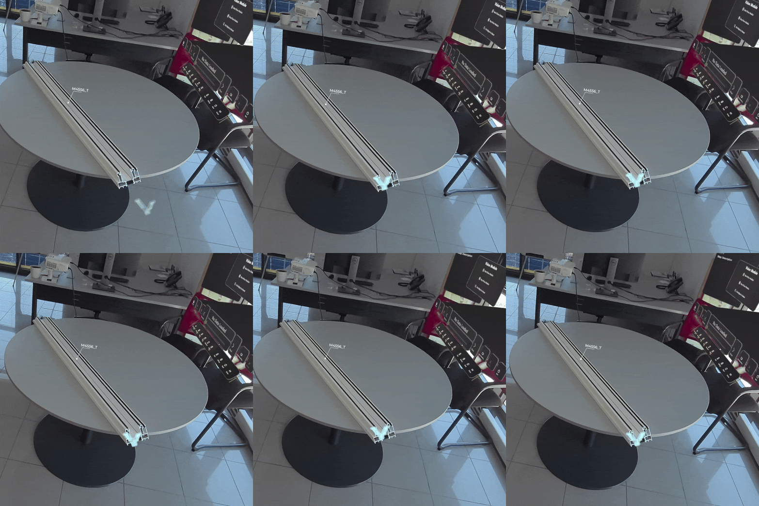
Example of mechanical corner insertion animation aligned to a real aluminium profile
What the Vision Module Enables
The Vision Module currently supports a complete perception loop:
- Capture – The XR device captures the live camera image, depth information and headset pose.
- Synchronise – The system keeps the image, depth map and camera metadata linked to the same real-world observation.
- Understand and track – Server-side AI isolates the object, selects the most likely CAD model and estimates the object’s 6D pose.
- Visualise in XR – The pose is returned to the XR device, where it can be shown as a world-space 3D bounding box, a CAD overlay, or another form of spatial guidance.
This workflow is important because video, depth and metadata do not automatically arrive together. In a live XR system, they travel through different paths and may be affected by different delays. The Vision Module therefore uses an explicit synchronisation strategy to make sure that the image, depth and pose result refer to the same captured moment.
Three Coordinated Pieces
The Vision Module is structured into three main parts.
1. XR Application-Side Pipeline
The XR application is responsible for capture and visualisation. It reads the live passthrough camera image, prepares it for streaming, attaches a unique frame identity, packages the corresponding depth information and sends everything to the server. When a pose result comes back, the XR application displays it in the headset.
This is the part that allows the system to close the loop: real-world capture goes out, object pose comes back, and the user sees the result directly in passthrough.
2. Vision Module Server
The Vision Module Server receives the live video stream, metadata and depth packets from the XR device. Its role is to reconstruct the correct RGB-D observation before any AI processing takes place.
This is a central part of the system. The server cannot simply assume that the newest metadata belongs to the newest video frame. Instead, it reads the frame identity from the video, retrieves the matching camera metadata, assembles the depth packets and rebuilds the synchronised RGB-D pair.
When possible, it also aligns depth to the colour camera view, so that RGB, depth and camera calibration describe the same observation. The synchronised frame is then sent to the tracking services.
3. GPU Inference Services
The GPU services turn a selected object into a tracked CAD-aligned pose.
The pipeline combines advanced AI models for object segmentation and visual matching with a custom TensorRT-accelerated tracking service based on FoundationPose. Using RGB, depth, camera calibration and CAD geometry, the service initialises the object’s 6D pose and tracks it over time.
This separation keeps the XR application focused on capture and visualisation, while the heavier AI processing runs on the server side.

How the Vision Module Works in a Live Session
In the current prototype, the Vision Module already operates as an integrated perception loop. A user selects a target object in passthrough, the server finds the synchronised RGB-D observation for that moment, and the AI services use this data to identify and track the object.
The process starts on the XR device. The user marks the object of interest, such as an aluminium profile, directly in the passthrough view. The Vision Module Server then reconstructs the matching RGB-D frame by linking the colour image, depth map, camera calibration and headset pose that belong to the same real-world observation.
Once this synchronised frame is available, the GPU services refine the selected object region, optionally match it to the correct CAD model, and initialise 6D pose tracking.
After initialisation, the system continues processing fresh synchronised RGB-D observations and sends updated object poses back to the XR device.
The result is spatial feedback inside the headset: a 3D box, CAD overlay, or future XR instruction can be placed directly on the real object. This demonstrates the main value of the Vision Module: it connects server-side AI perception with real-time XR guidance in the physical training environment.
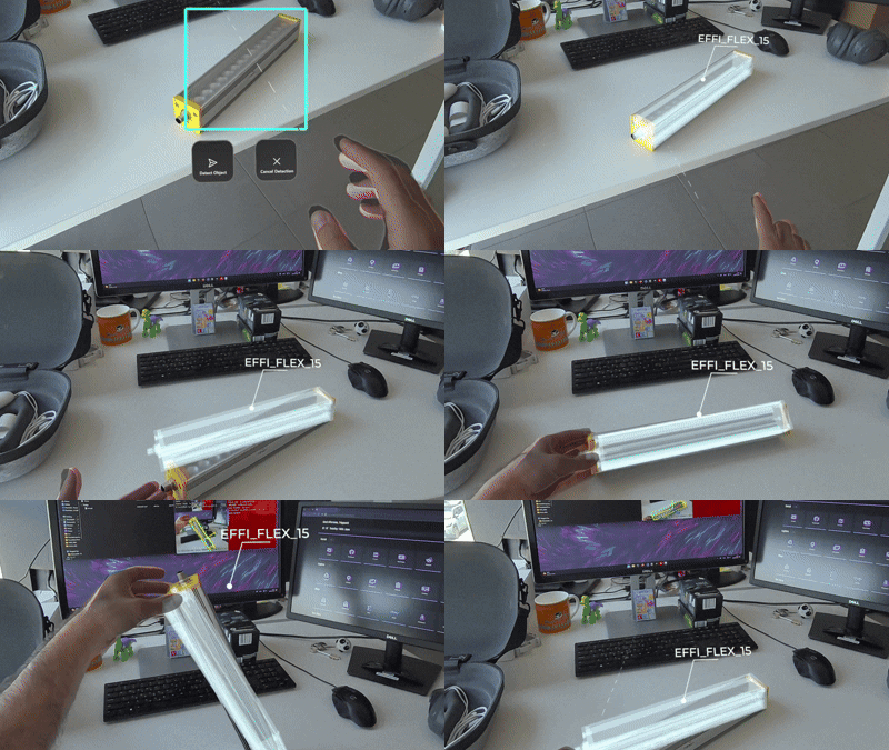
Live tracking loop showing object selection, pose estimation and XR overlay
Current Limitations
The current version is still under active development, and there is room for improvement in tracking robustness across different object scales.
Although the tracking service performs reliably in most tested scenarios, its robustness decreases for very small or very large objects. In these cases, the system may lose tracking or produce unstable pose estimates, jitter, drift or misalignment. These limitations are likely influenced by factors such as the amount of visible object detail, depth quality, CAD scale and the tracking parameters used for each object size.
Showing these failure cases is part of the development process. It helps make the limitations explicit and guides the next round of testing and tuning.
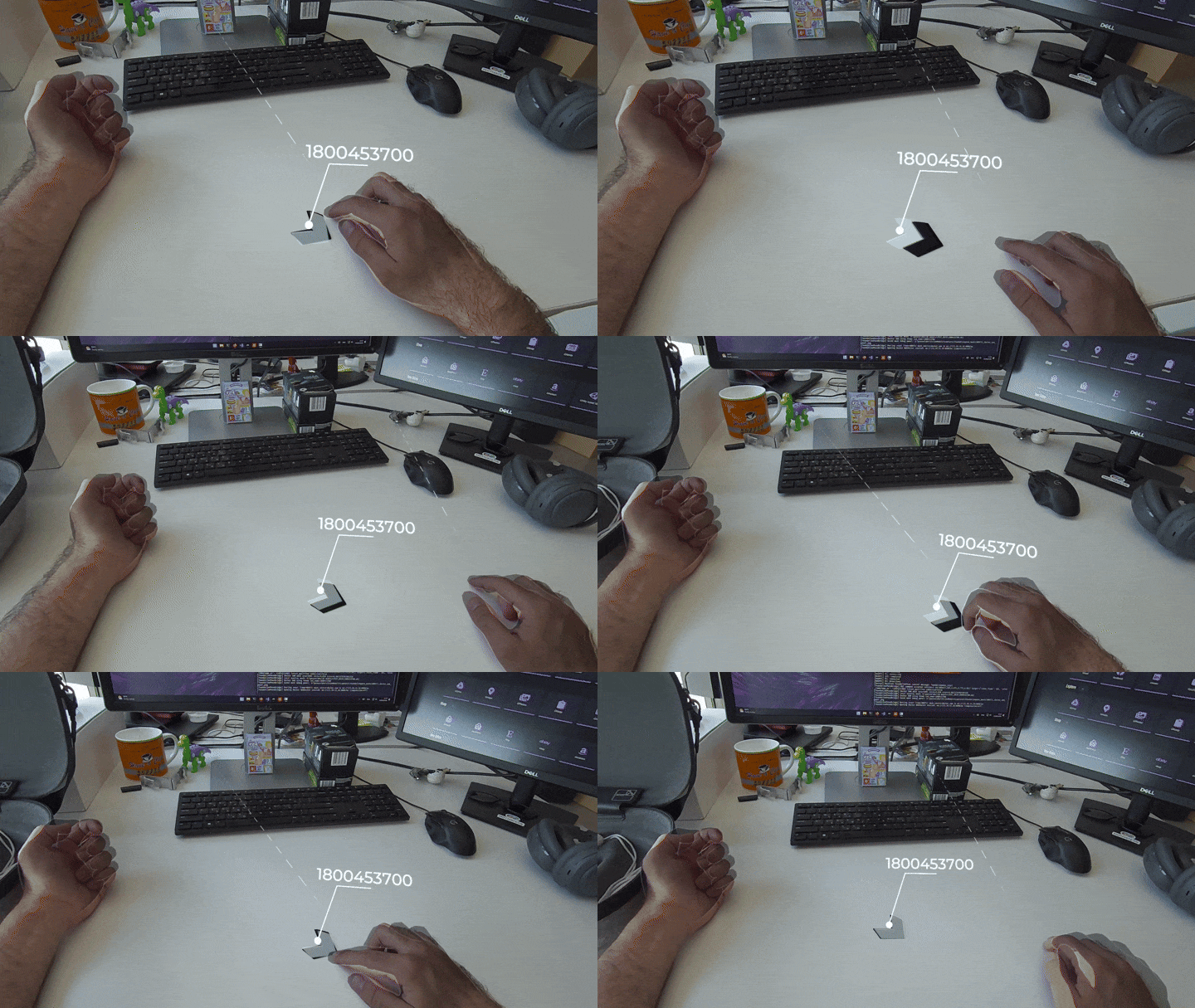
Vision Module Current Limitations
Next Steps
The next development phase will focus on improving robustness, asset readiness and integration.
A key priority is to test the tracking service across different object sizes and identify which settings need to change depending on object scale. This includes building per-object benchmarks, analysing failure modes and tuning tracking variables more systematically.
Another important step is improving CAD and matching readiness. The Vision Module depends on a reliable CAD library and good rendered references for automatic object selection. Expanding the CAD asset set and improving reference renders will make the matching stage more reliable.
Finally, the system needs to be streamlined for live training workflows. The goal is not only to make the technology work in a controlled test, but to make it practical for real training and maintenance sessions.
Towards Reliable Object-Aware XR Training
The Vision Module brings MOTIVATE XR closer to a form of training where digital instructions are not only displayed in the headset, but are spatially connected to the real task environment.
This matters because industrial training is not just about showing information. It is about helping users understand where to act, how to act, and whether they are interacting with the correct physical component.
By combining synchronised RGB-D capture, server-side AI tracking and in-headset visualisation, the Vision Module creates a foundation for XR guidance that is more precise, more contextual and more useful in real training and maintenance scenarios.
Author

D-Cube
Paschalis Choropanitis is a Software Engineer at D-Cube and works on XR applications for industrial training and interactive 3D systems. His work focuses on developing practical XR tools that support real-world learning, guidance, and collaboration in industrial environments, with particular interest in usability and immersive training workflows.


